The JPC-12 antenna comes with a ground plane ribbon, which you can separate into 3-4 strands. This works quite well if you have a good ground connection, like on freshly mown grass. However, not all portable locations offer a good ground connection – for example, I struggled to get a good SWR and good results when setting up the antenna in springy grass. We suspected that the reason for this, is that the ground ribbon is elevated, and there is a poor capacitance to ground. To improve that, the plan was to replace the ground ribbon with a better ground plane in order to get a better capacitance to ground.
There are two alternatives that I know of, to modify the ground plane of the JPC 12. One of these alternatives is a large flat metal plate, with screw terminals to attach wires to (it can be found at Martin Lynch and Sons here: https://www.hamradio.co.uk/radial-plate-for-the-jpc-12-antenna). Whilst this ground plate works well (and I used it often with my Dad’s JPC-12), the downsides with this ground plate is that it is fairly large, which is annoying if you want to be as lightweight as possible for POTA / SOTA, and the ground wire connections to the plate are a bit fragile. An alternative to this disk is a smaller ring, (available from WiMO here: https://www.wimo.com/en/chelegance-grounding-plate-disc) with holes to plug ground wires directly into it.
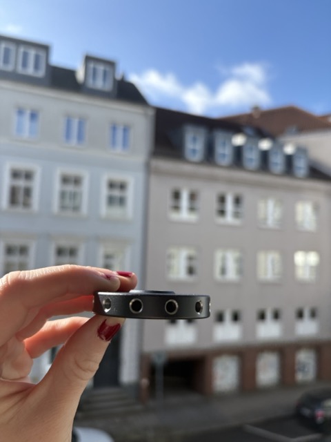
There are 12 holes in the disk, so we needed to prepare 12 ground wires. To do that we had to cut the ground wires to a desired length, and solder plugs onto the wires. Finally, it was time to test the setup, we put the disk onto the ground spike and attempted to screw on the next component of the JPC-12 antenna… it did not fit! The disk is too tall, and we could not build the antenna.
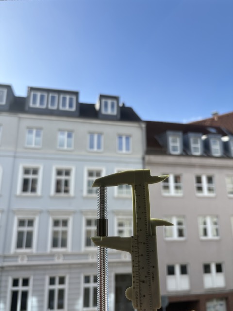
In order to fix it, the plan was to buy an M10 threaded rod and a coupling nut so that we could extend the ground spike of the JPC-12. We should then have enough room to screw on the new ground disk, and the following component of the antenna. We measured that the length of M10 rod that we needed to cut needed to be 4.5c, as show in the picture below (we used black tape to mark where the rod needed to be cut).
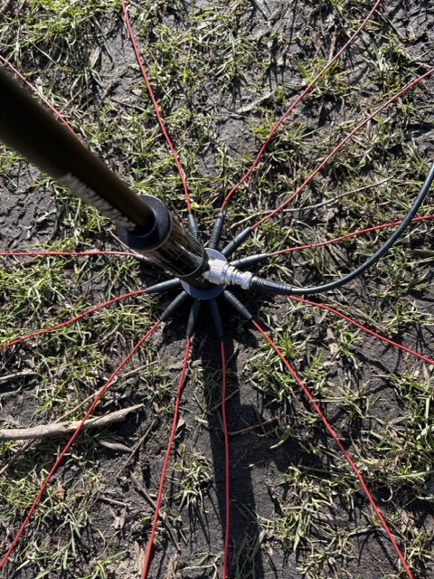
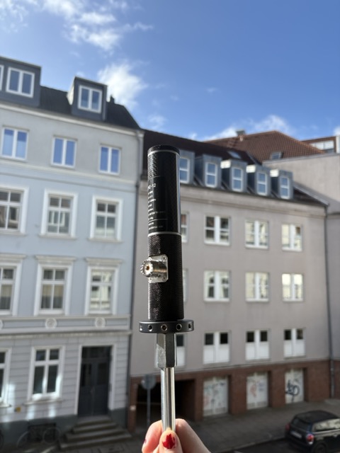
Once we had cut the rod to the correct size, we could assemble the antenna again. Now we had the ground spike attached to a coupling nut, attached to the short M10 rod, with the ground disk screwed on, and finally the next component. The overall assembly looks neat and compact. The ground disk is much smaller in diameter compared to the previously mentioned alternative ground plate.
The next step was to take the antenna outside and test it with the new radials. The SWR curve was flatter than we had seen when using the provided ground ribbon, we also achieved an SWR of 1:101 on the 20m band. The plugs on the ground wires felt very sturdy, plugging them into the disk required a small amount of force, but was easy enough. Overall I was very satisfied with the construction, and will make this my go-to setup when operating portable.